

Schema Relationships: Types & Examples
.png)
Every database stores data, but how that data is organized and connected determines how effectively it can be used. A database schema defines the structure of stored information, including its tables, fields, and rules, and most importantly, the relationships between tables. These relationships establish how data in one table relates to another, allowing for consistent, meaningful connections across the system and enabling powerful analysis.
Schema relationships make it possible to answer complex questions and maintain data integrity. They clarify dependencies, prevent inconsistencies, and support essential operations like joins, aggregations, and updates. For example, in a retail database, relationships can link customers to their orders, orders to the items they contain, and each item to its supplier. Without these connections, data would exist in isolation, making it difficult to extract useful insights.
This article explores schema relationships in detail: what they are, why they matter, and how they are represented in relational databases. It explains the main types such as one to one, one to many, and many to many, illustrates them with ER diagrams and practical business examples, and discusses best practices and common design mistakes. Finally, it compares relational and NoSQL systems and introduces the graph-based approach used by modern solutions such as PuppyGraph.
What is a Schema Relationship?
Before exploring the details of table structures, it is important to understand that databases are not just collections of tables. They are designed to represent real-world entities and their interactions. To make data meaningful and usable, we need a clear framework that defines both what data exists and how it relates.
Definition and Implementation
A schema relationship defines how data in one table corresponds to data in another table within a database. Relationships are essential for:
- Maintaining data integrity
- Enabling meaningful queries
- Reflecting real-world connections
In relational databases, schema relationships are typically implemented using foreign keys. A foreign key in one table references the primary key of another table, linking records across tables. The primary key uniquely identifies a record, while the foreign key acts as a pointer, creating a logical connection between tables.
Referential Integrity and Cardinality
Through these links, databases enforce referential integrity, ensuring that relationships remain consistent and preventing orphaned records. For example, an order should always reference an existing customer. Depending on schema rules, deleting a customer may be restricted or cascade changes to related orders.
Schema relationships also define cardinality, indicating how many records on one side correspond to records on the other side. Cardinality guides query structure and affects the efficiency of data retrieval. Furthermore, schema relationships encapsulate business rules, allowing the database to accurately reflect real-world processes.
Beyond Relational Databases
Although schema relationships are fundamental in relational databases, other database types handle relationships differently. NoSQL and graph databases represent relationships in ways that align with their storage and query models. Understanding schema relationships in relational systems provides a foundation for comparing these approaches.
Types of Schema Relationships
Relational databases primarily use three types of schema relationships: one-to-one, one-to-many, and many-to-many. Each type defines how records in one table relate to records in another table and the constraints that apply.
One-to-One Relationship
A one-to-one relationship occurs when a record in one table corresponds to exactly one record in another table. This type of relationship is less common but can be useful when splitting sensitive or optional data into separate tables. For example, a user table might store basic user information while a profile table stores extended details, such as address and phone number.
CREATE TABLE users (
  id SERIAL PRIMARY KEY,
  name TEXT
);

CREATE TABLE profiles (
  user_id INT PRIMARY KEY REFERENCES users(id),
  address TEXT,
  phone TEXT
);
users
profiles
In this example, each user has exactly one profile. Alice’s profile contains her address and phone number, while Bob’s profile contains his own. This ensures that each user’s personal information is stored separately but remains directly linked to their account, maintaining clarity and data integrity.
One-to-Many Relationship
A one-to-many relationship is the most common type in relational databases. A single record in a parent table can relate to multiple records in a child table, while each child record corresponds to only one parent. For instance, a customer can place multiple orders, but each order belongs to a single customer.
CREATE TABLE customers (
  id SERIAL PRIMARY KEY,
  name TEXT
);

CREATE TABLE orders (
  id SERIAL PRIMARY KEY,
  customer_id INT REFERENCES customers(id),
  order_date DATE
);
customers
orders
In this example, Alice has two orders (101 and 102) and Bob has one (103). Each order belongs to a single customer, but a customer can have multiple orders. This relationship is common in business contexts, like users and orders, or departments and employees.
Many-to-Many Relationship
Many-to-many relationships occur when multiple records in one table are related to multiple records in another table. Relational databases typically implement these using junction tables, which store pairs of foreign keys linking the related records.
students
courses
enrollments
In this example, Alice is enrolled in both Math and English, while Bob is enrolled only in Math. The enrollments table resolves the many-to-many relationship between students and courses. This design prevents data duplication and maintains referential integrity.
Weak Entities
Some entities depend entirely on another entity for their identity and cannot exist independently. These weak entities often have composite primary keys that include the foreign key of the parent table.
orders
order_items
In this example, order_items is a weak entity because it cannot exist without an associated order. Each item’s identity is partially derived from its parent order, using (order_id, line_no) as the primary key. Weak entities help maintain data consistency and avoid orphan records.
Schema Relationship with ER Diagrams
Entity-Relationship Diagrams (ERDs) provide a visual blueprint of schema relationships before database implementation. They help designers understand cardinality, optionality, and constraints, and identify potential flaws early in the design process.
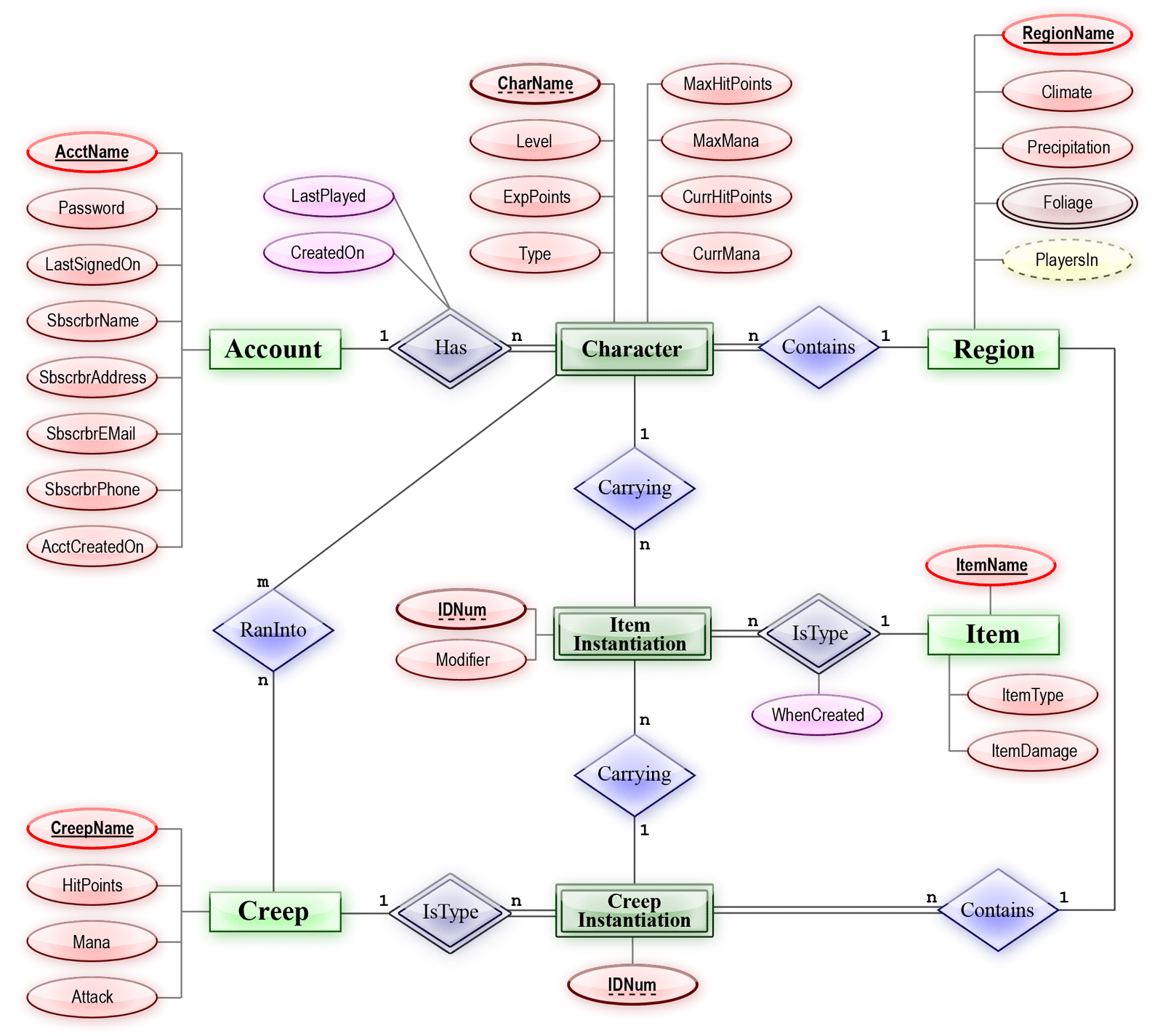
ERDs represent entities, such as users, products, or orders, as rectangles, with their attributes listed inside. Primary keys (PK) and foreign keys (FK) are clearly marked, indicating identity and the connections between entities. Relationships between entities are visualized with lines: a simple line represents a one-to-one relationship, a line ending with a crow’s foot represents a one-to-many relationship, and many-to-many relationships are expressed through an associative entity, which typically becomes a junction table in the database.
By using ERDs, designers can prevent modeling errors such as missing relationships, circular references, or incorrect cardinality. They also serve as a guide for translating the design into Data Definition Language (DDL) statements, ensuring that foreign keys and optionality rules are correctly implemented. Additionally, ERDs enhance communication across teams, allowing developers, analysts, and stakeholders to quickly grasp complex schemas.
Practical Examples of Schema Relationships
In an e-commerce database, users place orders that contain items. The user-to-order relationship is one-to-many, while the order-to-order item relationship is one-to-many as well. Products can be related to multiple categories, forming a many-to-many relationship.
In an education system database of a university, students enroll in courses through a many-to-many relationship resolved by an enrollment table. Each course may have multiple instructors, leading to another many-to-many relationship.
In an HR system, employees belong to departments, forming a one-to-many relationship. Each employee may have a profile or benefits record, which can be modeled as a one-to-one relationship.
In a healthcare system, patients schedule appointments with doctors, creating a many-to-many relationship managed through an appointments table. Medical records link to a single patient (one-to-one), while each doctor may treat many patients (one-to-many).
In a financial or banking system, customers hold multiple accounts (one-to-many), and accounts can be linked to multiple joint owners, forming a many-to-many structure that supports complex authorization models.
In a cybersecurity monitoring system, users, devices, and network events are interlinked. A single device can generate many alerts (one-to-many), each alert can be associated with multiple threat indicators (many-to-many), and incidents may aggregate multiple alerts to trace attack paths.
These examples show how relationships reflect real-world interactions and support queries, reporting, and data integrity.
Best Practices for Defining Schema Relationships
Designing effective schema relationships is crucial for building reliable and maintainable databases. Key best practices include:
- Define Clear, Explicit Relationships
Use foreign keys at the database level, and prefer surrogate keys for stability. Index keys to optimize joins, and plan optionality early to distinguish mandatory and optional links, which improves consistency and clarity. - Balance Normalization and Practicality
Normalize to reduce redundancy, but avoid over-normalization that complicates queries. Selective denormalization can improve performance for reporting or read-heavy operations. - Plan Cascading Actions and Test Relationships
Cascading actions are database rules that automatically propagate updates or deletions from a parent table to related child tables (e.g., ON DELETE CASCADE). Configure cascading carefully. While they can simplify data maintenance, improper use may cause unintended data loss. Always test with realistic datasets to confirm that constraints, cascades, and optional relationships behave as expected. - Document and Maintain Consistency
ER diagrams, consistent naming conventions, and clear documentation make schemas easier to maintain and evolve, reducing errors in future modifications.
By following these principles, databases remain robust, intuitive, and adaptable to evolving business needs.
Common Mistakes in Schema Relationships
Even experienced designers can fall into predictable pitfalls. Common mistakes include:
- Missing or Improper Foreign Keys
Relying solely on application logic can lead to orphaned records. Mismanaging cardinality, such as skipping junction tables or overusing one-to-one relationships, complicates queries and reduces flexibility. - Nullable Foreign Keys and Over-Normalization
Allowing foreign keys to be null when relationships are mandatory introduces ambiguous data. Over-normalization splits data excessively, slowing queries. Using unstable natural keys, like emails, risks breaking relationships when values change. - Misconfigured Cascading Actions
Improper cascading deletes or updates can remove critical data unintentionally. Testing and careful planning ensure cascading rules align with business requirements.
Schema Relationships in NoSQL vs Relational Databases
Relational databases enforce relationships through foreign keys and constraints, ensuring referential integrity. In contrast, NoSQL systems handle relationships differently, reflecting their storage and query models:
- Document Databases
Document databases store data as flexible, nested documents rather than fixed tables. Relationships are expressed either by embedding related data within a single document or by referencing other documents through identifiers. Embedding simplifies reads and updates but can cause duplication, while referencing preserves normalization but relies on application-level joins. The database does not enforce referential integrity, leaving relationship management to the application. - Key-Value and Column-Family Stores
Key-value and column-family databases both minimize or eliminate explicit schema relationships in favor of performance and scalability. In key-value stores, data exists as isolated key-value pairs without any built-in links; relationships must be handled entirely by the application through naming conventions or embedded data. Column-family databases, such as Cassandra and HBase, extend this model by grouping related columns under shared row keys, allowing limited co-location of related data. Instead of enforcing foreign keys or joins, they use denormalization to store related data together for faster, query-specific access, trading normalization and integrity for performance. - Graph Database
Graph databases represent both data and relationships directly, storing entities as nodes and connections as edges. Edges are treated as first-class citizens, enabling efficient traversal across interconnected data. This model supports complex, relationship-heavy queries that are often cumbersome or slow in relational or document-based systems. Unlike other databases where relationships are implicit or application-managed, graph databases explicitly store and index relationships, allowing for sophisticated pattern matching and pathfinding operations.
Comparing approaches highlights the benefits of relational integrity while showing why different database types adopt alternative strategies to model relationships effectively. However, as data models continue to evolve, a new approach has emerged that builds graph structures directly on top of existing relational schemas and their relationships, making it easier to explore connected data using common graph query languages. This is what we will introduce next.
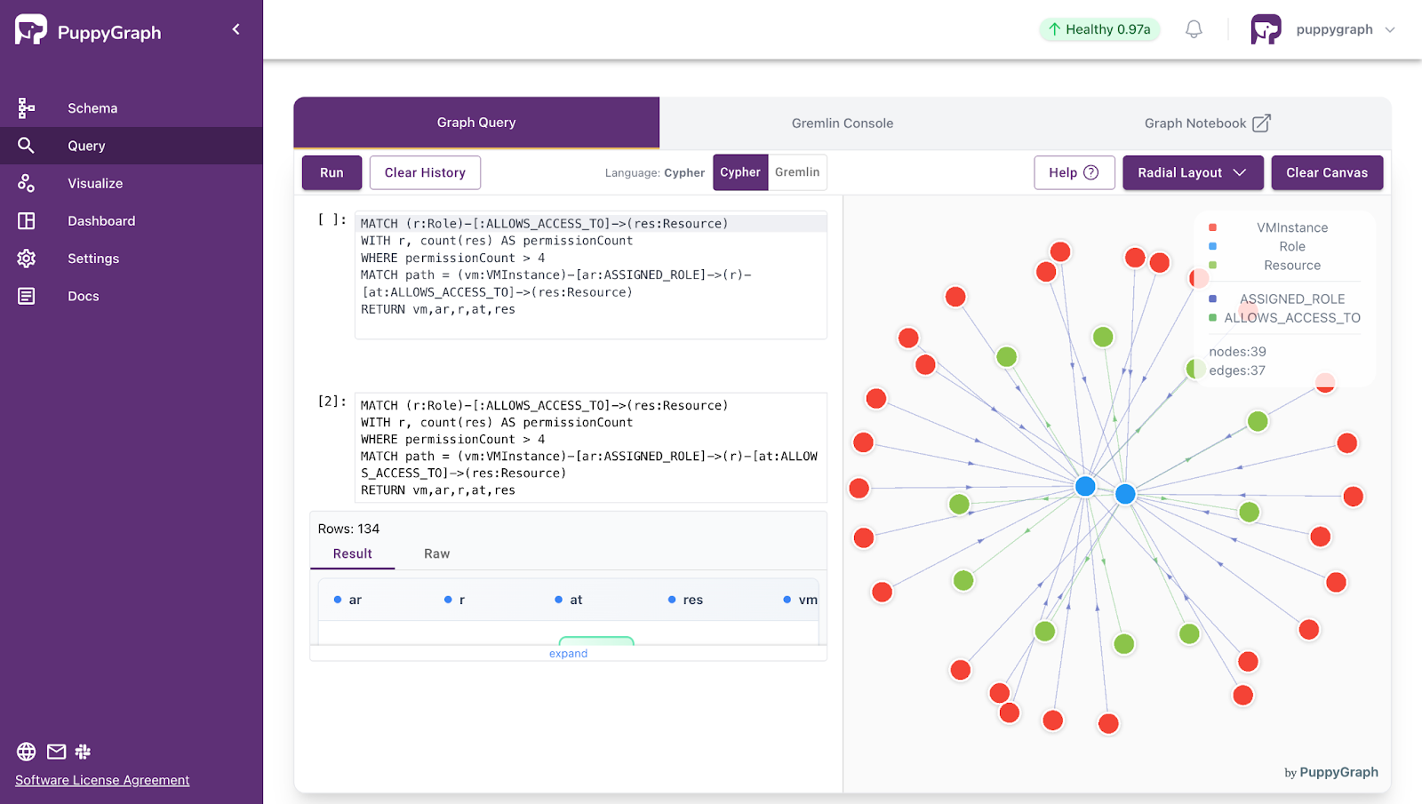
PuppyGraph: Query Your Relational Data as a Graph
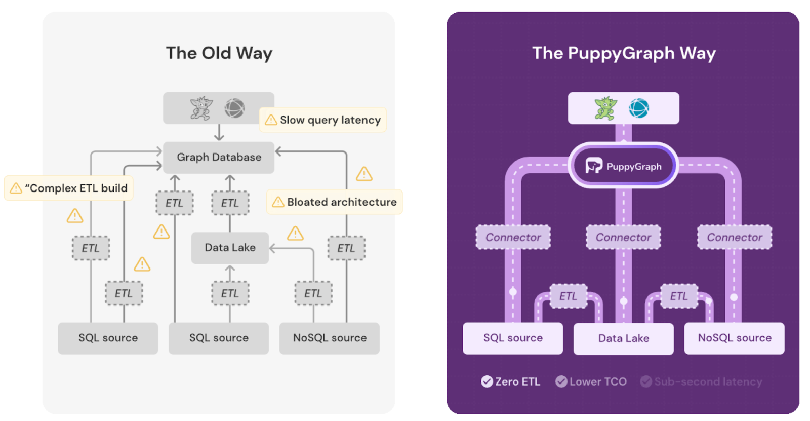
PuppyGraph is the first and only real-time, zero-ETL graph query engine in the market, enabling data teams to quickly deploy and query existing relational data stores as a unified graph model. In PuppyGraph, you can define the structure of your graph directly through a simple JSON-based schema, without the need to move or modify any data in your existing systems. With this schema, you can interpret your existing tables, views, and datasets as a connected graph, making complex relationships easy to model and explore.

A PuppyGraph Schema defines how your source data maps into a graph structure within a catalog, which specifies the connection parameters and authentication details required to access the data source. The converted graph structure consists of:
- Nodes represent entities such as users, products, or accounts, created directly from existing tables or views.
- Edges represent relationships between entities, such as purchased, friend, or transferred, and can include properties like timestamps, types, or weights.
With this mapping, queries that would require multiple JOINs in a traditional database, like “find customers who made orders containing a particular product,” can be expressed as a single graph traversal in PuppyGraph.
MATCH (c:Customer)-[:PurchaseOrder]->(o:Order)-[:ContainsProduct]->(p:Product)
WHERE p.product_name = "Chai"
RETURN elementId(c), c.company_name, c.contact_name
In PuppyGraph, schemas are defined entirely through JSON files, requiring no data migration or structural changes to your existing source systems. This makes graph modeling lightweight, and also highly flexible, since multiple graph models can be created from the same data source simply by defining different JSON schema files. As your data evolves, your graph models can evolve just as easily.
PuppyGraph also includes a Graph Schema Builder, an intuitive visual interface for defining nodes, edges, and their attributes. You can visually create and connect nodes and relationships, or edit the underlying JSON schema for precise control. Both technical and non-technical users can easily design graph schemas that reflect real-world business logic.
With PuppyGraph, exploring complex relationships and patterns in your data becomes much simpler. Here are some key benefits it may bring to your team:
Key PuppyGraph capabilities include:
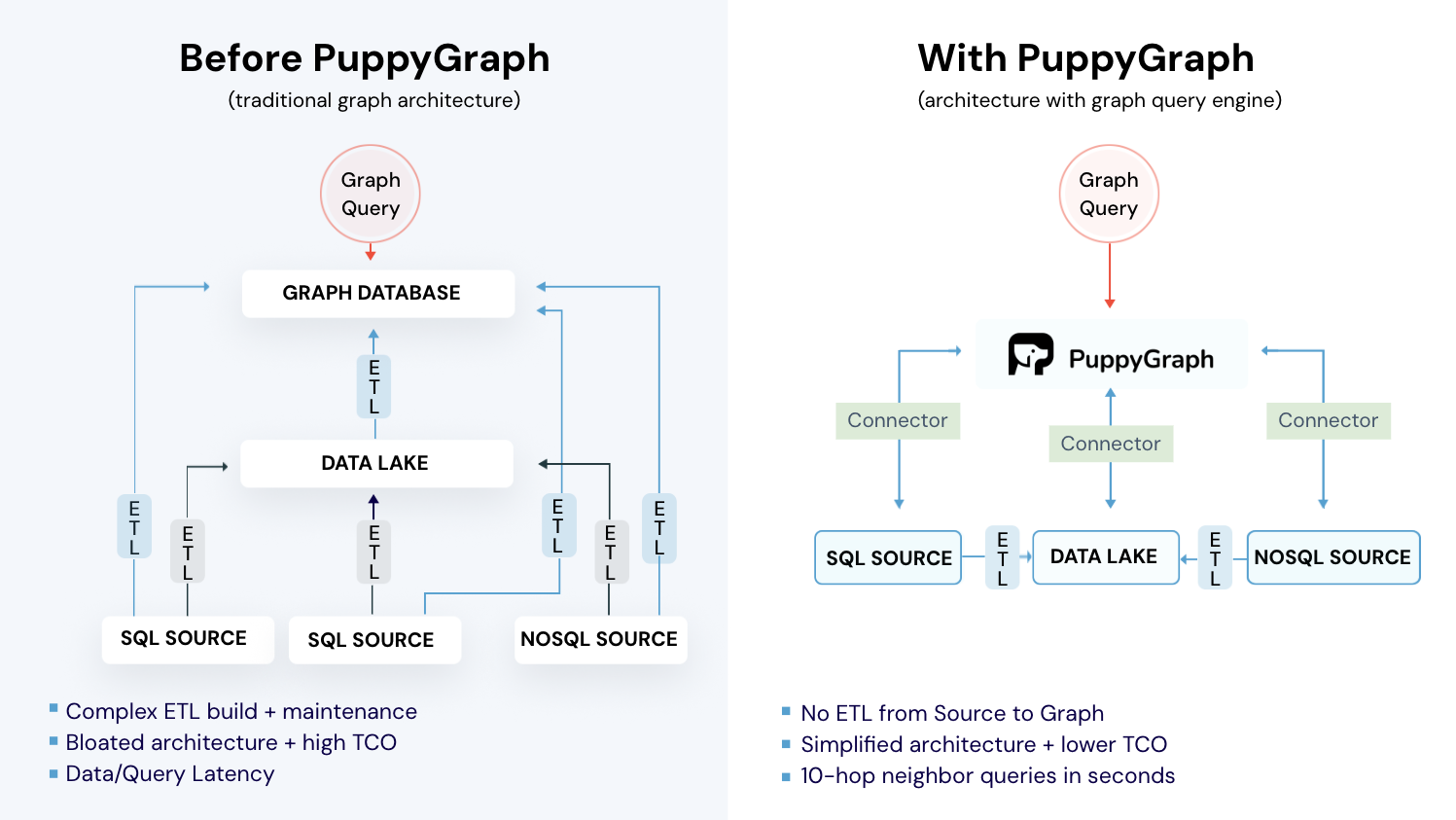
- Zero ETL: PuppyGraph runs as a query engine on your existing relational databases and lakes. Skip pipeline builds, reduce fragility, and start querying as a graph in minutes.
- No Data Duplication: Query your data in place, eliminating the need to copy large datasets into a separate graph database. This ensures data consistency and leverages existing data access controls.
- Real Time Analysis: By querying live source data, analyses reflect the current state of the environment, mitigating the problem of relying on static, potentially outdated graph snapshots. PuppyGraph users report 6-hop queries across billions of edges in less than 3 seconds.
- Scalable Performance: PuppyGraph’s distributed compute engine scales with your cluster size. Run petabyte-scale workloads and deep traversals like 10-hop neighbors, and get answers back in seconds. This exceptional query performance is achieved through the use of parallel processing and vectorized evaluation technology.
- Best of SQL and Graph: Because PuppyGraph queries your data in place, teams can use their existing SQL engines for tabular workloads and PuppyGraph for relationship-heavy analysis, all on the same source tables. No need to force every use case through a graph database or retrain teams on a new query language.
- Lower Total Cost of Ownership: Graph databases make you pay twice — once for pipelines, duplicated storage, and parallel governance, and again for the high-memory hardware needed to make them fast. PuppyGraph removes both costs by querying your lake directly with zero ETL and no second system to maintain. No massive RAM bills, no duplicated ACLs, and no extra infrastructure to secure.
- Flexible and Iterative Modeling: Using metadata driven schemas allows creating multiple graph views from the same underlying data. Models can be iterated upon quickly without rebuilding data pipelines, supporting agile analysis workflows.
- Standard Querying and Visualization: Support for standard graph query languages (openCypher, Gremlin) and integrated visualization tools helps analysts explore relationships intuitively and effectively.
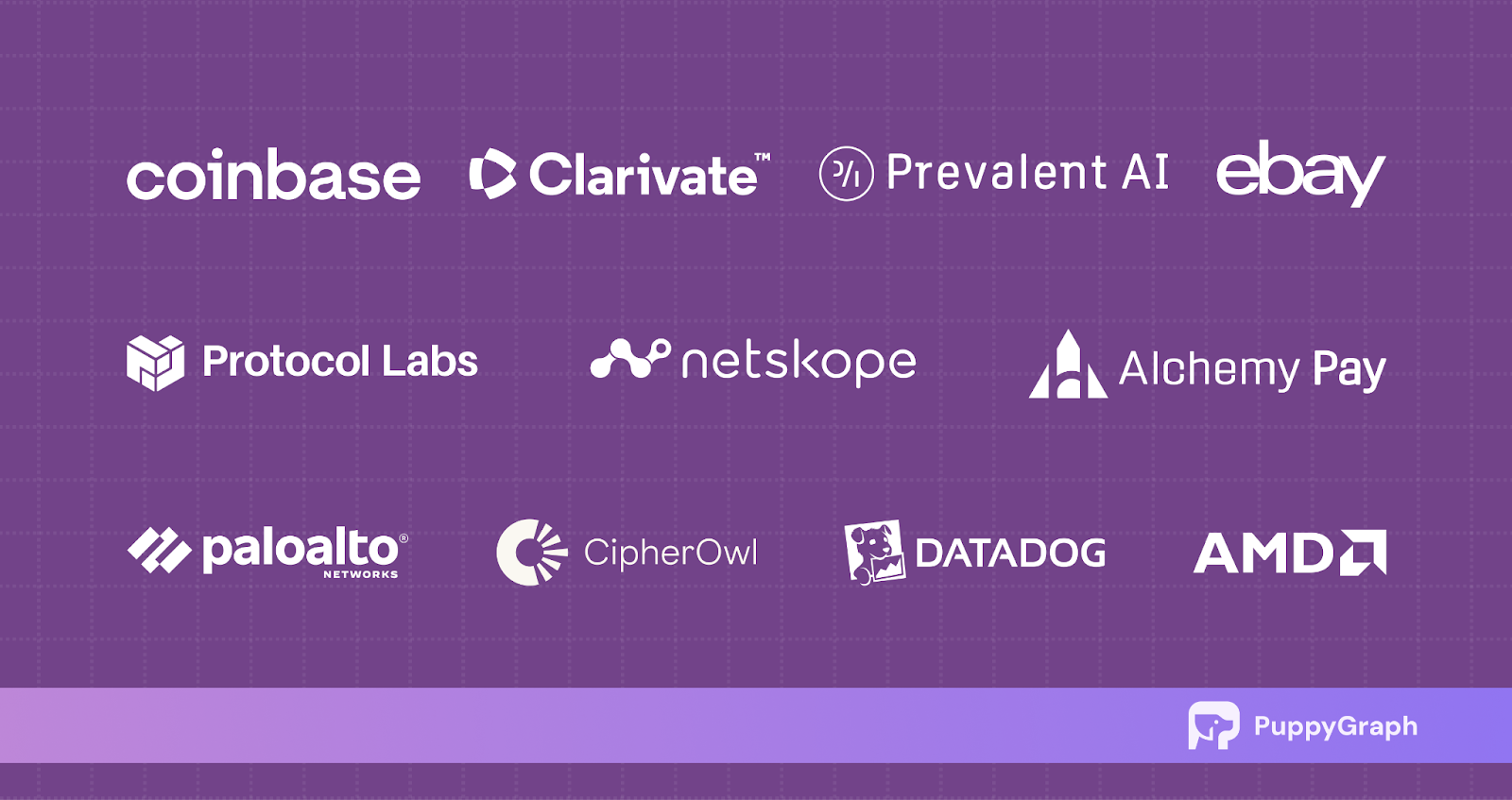
- Proven at Enterprise Scale: PuppyGraph is already used by half of the top 20 cybersecurity companies, as well as engineering-driven enterprises like AMD and Coinbase. Whether it’s multi-hop security reasoning, asset intelligence, or deep relationship queries across massive datasets, these teams trust PuppyGraph to replace slow ETL pipelines and complex graph stacks with a simpler, faster architecture.
As data grows more complex, the most valuable insights often lie in how entities relate. PuppyGraph brings those insights to the surface, whether you’re modeling organizational networks, social introductions, fraud and cybersecurity graphs, or GraphRAG pipelines that trace knowledge provenance.
Deployment is simple: download the free Docker image, connect PuppyGraph to your existing data stores, define graph schemas, and start querying. PuppyGraph can be deployed via Docker, AWS AMI, GCP Marketplace, or within a VPC or data center for full data control.
Conclusion
Schema relationships are the backbone of effective database design. They define how data is connected, enforce integrity, and support efficient querying and maintenance. Mastering one-to-one, one-to-many, and many-to-many relationships enables the creation of robust, consistent, and scalable relational databases.
If you want to explore your relational data using a graph-based approach, get started with our forever-free Developer Edition to run graph queries directly on your existing relational data, or book a demo to see how PuppyGraph makes complex relationship analysis intuitive and efficient.

Hao Wu is a Software Engineer with a strong foundation in computer science and algorithms. He earned his Bachelor’s degree in Computer Science from Fudan University and a Master’s degree from George Washington University, where he focused on graph databases.

Get started with PuppyGraph!


Developer Edition
- Forever free
- Single noded
- Designed for proving your ideas
- Available via Docker install
Enterprise Edition
- 30-day free trial with full features
- Everything in developer edition & enterprise features
- Designed for production
- Available via AWS AMI & Docker install